What is an EGR system?
The high temperature in the combustion chamber usually exceeds 2500 degrees Fahrenheit. Nitrogen(N2) and oxygen(O2) combine to form nitrogen oxides(NOx). NOx is a harmful gas that reacts with hydrocarbons in the atmosphere to generate ozone(O3) under sunlight.
Once the air-fuel mixture burns during the power stroke, the combustion chamber produces exhaust gases. The tail gas is “tail gas”. Throw “; the pressure of the combustion chamber during the exhaust stroke. The exhaust gas(including NOx) is finally discharged into the atmosphere through the exhaust valve and exhaust channel through the exhaust system.
The EGR system returns part of the exhaust gas(6~10%) to the intake system through the EGR valve, and finally enters the combustion chamber. The exhaust gas is inert. That is, they will not burn in the combustion chamber. In addition, exhaust gas originally occupies the space that air can enter. This reduces the amount of intake air that can be used for the combustion process during each power stroke; this in turn reduces the peak combustion temperature. This will result in lower NOx emissions.
One of the auxiliary advantages of using the EGR system is that it allows a shorter time to reduce shocks.
Key components of EGR system:
a) Tail gas channel
b) EGR valve
c) Sensor – position, feedback
d) EGR channel
In a serial engine, the exhaust passage is connected to the intake pipe through an external pipe. The V-type engine has casting channels in the exhaust and suction mechanisms.
Thesis Overview
- EGR valve type
a. Back pressure
i. Barotropic
Ii. Sound pressure(vacuum)
b. Computer control
i. 1 – Solenoid valve
ii. 2 Solenoid valve
Ii.3 Solenoid valve
Iv. Linear EGR
- Position sensor type
a. EGR valve position sensor(EVP)
b. Pressure feedback EGR sensor(PFE)
- OBDII monitoring strategy
a. O2 sensor
b. Delta pressure feedback EGR sensor(DPFE)
c. MAP sensor
- Diagnosis
a. Vacuum pump and measure
b. General DTC
EGR valve type – back pressure
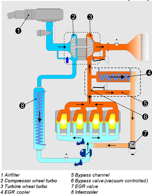
Refer to the diagram above – after the valve is opened, the exhaust gas(2) enters the inspiratory organ(3). In some cases, the exhaust gas mixes with the intake air in front of the throttle valve. EGR valve can be positive back pressure. Push and pull; open the valve; or it can be “applied vacuum” through negative back pressure, i.e. vacuum port(4); the valve opens.
EGR valve type – computer controlled
In this type of EGR, the PCM controls the on/off of the EGR(1-solenoid valve) vacuum source. In the dual solenoid valve, the second solenoid valve controls the amount of vacuum to be applied.
3 Spool design – There are 3 small holes, middle holes and large holes, and each spool controls the opening and closing of this hole. In addition to being completely closed, seven different flow rates are generated.
Linear EGR design uses solenoid valve with adjustable pulse width to precisely control exhaust flow.
Position sensor type
Most OBDII systems have a feedback circuit for the actual EGR valve position.
EGR valve position sensor(EVP) – located at the top of the EGR valve. The sensor is just a potentiometer, which sends a signal to the PCM according to the open/close position of the EGR valve.
Pressure feedback EGR sensor(PFE) – located on the exhaust side of the EGR valve. When EGR valve is opened; the pressure on the exhaust side will be higher than when the valve is closed. The PFE converts these pressure data into voltage signals and transmits them to the PCM.
OBDII monitoring strategy
All OBDII systems perform diagnostic tests to ensure that the EGR valve operates correctly. The three overview methods/sensors all use local dynamic changes, such as the oxygen level or pressure to send the PCM the EGR valve normal function signal.
When the oxygen sensor EGR valve is opened, the oxygen level detected by the oxygen sensor must drop.
DPFE sensor – install a measuring hole on the suction side of the EGR valve. If the EGR valve is open, the pressure of this orifice should be lower than when the EGR valve is closed. Because after the EGR valve is opened, the orifice will be exposed to partial vacuum. The DPFE sensor measures this pressure difference and connects the PCM.
When the MAP sensor EGR valve is opened, the exhaust gas will flow to the intake hose. This will change the vacuum level of the intake pipe and the fuel adjustment for charging. AP sensor “; notification”; these changes are acceptable. If they fall to the pre calculated level, “0” will be given; thumbs up “; eGR function.
diagnosis
There may be some problems with the EGR system. If the EGR valve is in the closed position or the exhaust flow is limited, the EGR system will not work properly, the NOx level will rise and may explode. The EGR valve is stuck in the open position. In addition to the engine output problem, rough idling and overspeed will occur at low speed.
The function of EGR system can be verified through the combination of vacuum pump and pressure gauge. California smoke inspection project requires EGR function test on TSI – 1995 and previous vehicles. There are basically two items to consider: a) whether the EGR valve can maintain vacuum; b) whether the engine is closed when vacuum is applied. If the vehicle cannot maintain vacuum – there is a problem with the EGR valve or EGR channel. If the engine doesn’t stop, there is a problem with the exhaust passage.
In the PCM, if there is a problem with the EGR system, the general DTC: P400/P0401/P0402 will be set.
Reference documents:
a) Inspector Training Level 1, STI, 28 sheets – Exhaust Gas Recirculation(EGR) system
b) Wikipedia
c) Various links mentioned in the body of the article